


Tech Notes
Applies to Models: 7224, 7234, 7548, 7794, 7796 and 7796HC
Compensating the Amplifier
to the Load for CC Operation
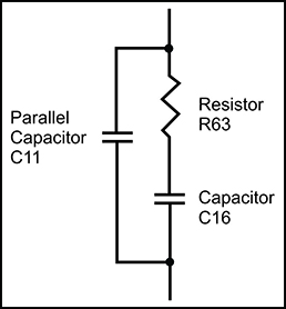
Figure 1: Factory-installed default RC network
Controlling Compensation for CC Operation
This article describes the method for determining and setting proper compensation when operating an AE Techron 7000 Series amplifier in Controlled Current mode. For basic information about Controlled Current and Controlled Voltage modes of operation, please see the Tech Note “Controlled Voltage vs. Controlled Current Modes of Operation.”
AE Techron 7000 Series amplifiers can be configured for either Controlled Voltage (CV) or Controlled Current (CC) mode of operation. When operating the amplifier in Controlled Voltage (CV) mode, compensation is not required. However, when operating in Controlled Current (CC) mode, the amplifier load becomes an integral part of the system. In order to ensure system stability and to control available bandwidth, compensation via an RC network is required for CC operation. The following steps will allow you to safely and effectively compensate your amplifier for operation in CC mode.
STEP 1: Check Amplifier Operation in CV Mode
We recommend that you power-up and enable the amplifier in Controlled Voltage mode without attaching a load before configuring your amplifier for Controlled Current operation. This will allow you to verify that the input signal and the amplifier are operating correctly.
Once this initial check is completed, power down the amplifier and access the configuration controls for the amplifier. Depending on the amplifier model, these controls can be jumpers or DIP switches located on the amplifier’s main board, or DIP switches located on the amplifier back panel. Consult the “Advanced Configuration” section of your product’s Operation Manual for more information.
Locate the control for the amplifier’s Operation Mode (CV or CC) and the control for the amplifier Compensation. One of two compensation settings can be selected: CC1 which enables the factory-installed RC network (see Figure 1), or CC2 which allows installation of a custom RC network.
STEP 2: Determine Required Compensation
When operating an amplifier in Controlled Current mode, the load becomes an integral part of the system. In order to determine the required compensation for your load, begin by consulting the following table to determine the approximate compensation capacitance (C) required based on the inductance of your load:
| Compensation Capacitance (Cc) |
Load Inductance (L) | ||
| <200 microHenries | >200 microHenries to <1 milliHenry | >1 milliHenry | |
| 0.001 microfarad | 0.01 microfarad | 0.1 microfarad | |
NOTE: Load Resistance (R) is assumed to be <5 ohms.
STEP 3: Determine if Default or Custom Compensation is Required
If your load inductance is between 200 microHenries and 1 milliHenry and your load resistance is less than 5 ohms, then you can likely use the default compensation provided by the amplifier’s factory-installed RC network. To select the factory-default compensation, please see STEP 4 below.
If your load inductance falls outside of the mid-range, or if your load resistance is greater than 5 ohms, then you must calculate your required compensation. If, after calculating your required compensation, you determine that the default compensation will be insufficient for your load, then you will need to enable and install a custom RC network. See STEP 6.
STEP 4: Verify Suitability of Default Compensation (CC1) – optional
If desired, the following values of the components contained in the default RC network can be used with the formulas provided in STEP 5 below to verify the suitability of the default compensation for your uses.
- Compensation Resistor: 68.1k ohms
- Compensation Capacitor: 47 nF
- Parallel Capacitor: 100 pF
STEP 5: Calculating Values for an RC Network for Custom Compensation (CC2)
If the default RC network does not provide suitable compensation for your intended load, you will need to install a custom RC network that is matched to your load. This network will require two components (a resistor (R) and a capacitor (C)) to be installed on the main board. To calculate the approximate values required for each component, use the following formulas.
COMPENSATION FORMULAS:
To find the value for the resistor (Rc) in the RC network:
Rc = 20,000 x 3.14 x L x BW
where:
Rc is compensation resistance in ohms.
L is load inductance in henries.
BW is bandwidth in hertz.
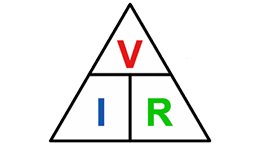
To find the value for the capacitor (Cc) in the RC network:
Cc = L/ (R x Rc)
where:
Cc is compensation capacitance in farads.
L is load inductance in henries.
R is resistance of load in ohms.
Rc is compensation resistance in ohms.

Figure 2: Custom compensation component locations

Figure 3: Compensation effects on waveform

Figure 4: Squarewave showing a decrease in R is required

Figure 5: Squarewave showing an increase in R is required

Figure 6: Squarewave showing an increase in C is required
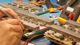
STEP 6: Installing and Enabling the Custom RC Network
Once an approximate value for Rc and Cc have been computed, these values will need to be evaluated. To do this, you will need to install the custom components on the amplifier’s main board and enable the alternate compensation network (CC2).
The main board can be accessed by removing the amplifier top cover (7200 series amplifiers), or by removing the amplifier’s front panel (7548, 7794, 7796, and 7796HC amplifiers). Instructions for accessing the amplifier main board can be found in the product’s Operation Manual.
First, locate the locations on the amplifier main board to install the custom components. For all current 7000 series amplifiers, the locations are labeled R5 and C2 and are located as shown in Figure 2. For the custom compensation locations for older 7000 series amplifiers, please consult your product’s Operation Manual.
Figure 2: Custom compensation component locations.
Once components with the required values have been installed, you must configure the amplifier to use this compenation network. Depending on your product model and year of manufacture, the control for this setting may be a jumper or DIP switch locaterd on the amplifier main board or a DIP switch located on the amplifier back panel. Please consult your product’s Operation Manual for the location of the compensation control.
Set the compensation control to the CC2 setting to enable your custom compensation network.
STEP 7: Optimizing the Compensation Values
Remember the load you are connecting is a part of the system and the amplifier should not be turned on without the load being connected.
After installing the components, check to ensure that the Mode of Operation control is set to Current Mode (this is DIP switch #1 on current 7000 series amplifiers). Make sure your load is connected to the amplifier outputs, then power up the amplifier without signal input.
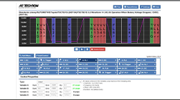
To begin testing, input a square wave with a frequency of 100 Hz to 1 kHz, or a squared pulse at a low level (typically 0.25 to 2.0 volts). A limited-rise-time, repetitive pulse of low duty cycle is preferred.
Observe the output current through a current monitor or current probe. Look for clean transition edges. The presence of ringing or rounding on the transition edges indicates compensation problems. (See Figure 3.)
If a change in compensation is necessary, an adjustment to the resistor component of the Compensation circuit is probably required.
If the output current waveform is ringing, the circuit is underdamped: You have too much gain and should lower the resistance (see Figure 4).
If the output current waveform is rounded, the circuit is overdamped: You have too little gain and should increase resistance (see Figure 5).
If the output current waveform is neither underdamped or overdamped, but the top of the squarewave is not level, then you should instead increase the capacitor value (see Figure 6).
When making adjustments:
- Resistor: Increase or decrease resistance values in increments of +/- 10%.
- Capacitor: Incrementally increase capacitor values by a factor of 2 or 3.
After final adjustments have been made to the circuit, the final waveform for your planned application should be tested to confirm the amplifier’s compensation setting.
NOTE:
- If possible, use 1% metal film resistors. AE Techron discourages installation of potentiometers in the resistor location of the compensation circuit because this can decrease stability and may increase inductance.
- The parallel capacitor in the RC network serves to increase stability, but can be removed, if it is not required for system stability. If the parallel capacitor is used, it will usually decrease the value of resistance needed.
- In multiple amplifier systems, expect to decrease the value of R63 in series systems by 1/2.
For additional assistance in modifying amplifier compensation, please contact AE Techron Technical Support at [email protected].