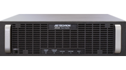
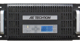
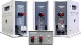
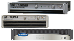
Did you know that most of our amplifiers can be customized via DIP switches?
In a previous article, we outlined the DIP switch configurations for our 72XX/77XX linear amplifiers. But our 8000 Family of switch-mode amplifiers have a much broader range of configurations.
A DIP switch is a manual electric switch designed to be used on a printed circuit board along with other electronic components. It is commonly used to customize the behavior of an electronic device for specific situations.
AE Techron’s 8300, 8500, and 8700 Series all share the same DIP switch configurations. This flexible design allows you to choose from a range of field-configurable options, including:
- Enable the unbalanced or balanced signal input connections, or use both inputs.
- Select DC-coupled or AC-coupled operation.
- Enable DC Servo to ensure DC offset remains at zero and safely drive coils and transformers.
- Select Controlled-Current or Controlled-Voltage modes of operation.
- Select an alternate compensation network for Controlled Current operation designed for loads from 1 mH to 5 mH.
- Install a custom compensation network for Controlled Current operation.
- Limit current output via programmable current limits.
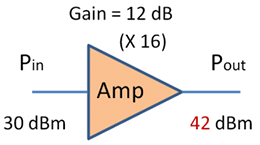
- Adjust the amplifier gain from 0.16 to 40 in increments of 0.16.
- Select and enable a synthetic impedance from 0.125 ohms to 0.875 ohms.
DIP Switch Configurations
In this article, we will highlight the DIP switch configurations available on our 8000 Family switch-mode amplifiers. For more detailed information, you can access the unit operator’s manual which is available as a PDF on the individual product pages.
SW#1: Unbalanced Input
When the unbalanced BNC input connector is enabled, it can be used to send an input signal to the amplifier. Disabling an unused input connector can help to minimize noise going into the amplifier.
SW#2: Balanced Input
When the balanced WECO input connector is enabled, it can be used to send an input signal to the amplifier.
SW#3: DC Servo
The DC Servo function ensures that no DC offset is present at the signal output (-3 dB at 3 Hz). Select DC Servo when driving transformers or other coils.
SW#4: Operation Mode
The Operation Mode DIP switch default is Controlled-Voltage mode, and the amplifier’s output voltage will be controlled by its input voltage signal. The switch can be changed to Controlled-Current mode, and the amplifier’s output current will be controlled by its input voltage signal.
SW#5: Compensation Network 2
When the amplifier is used in Controlled-Current mode, the current control loop is tuned with an RC network. The factory default network (Compensation Network 1) provides 100k ohm resistance and 2.2 nF capacitance and should be used with loads that are 75 μH to 500 μH.
SW#6: Compensation Network 1
If the default network is not adequate for your application and load, the Compensation Network 1 switch can be turned off and the Compensation Network 2 switch can be used to enable a network that provides 100k ohm resistance and 10 nF capacitance and should be used with loads that are 500 μH to 2 mH.
NOTE: Enable ONLY Compensation Network 2 (SW#5) or ONLY Compensation Network 1 (SW#6). Both compensation networks should NOT be enabled simultaneously.
SW#7: Control Configuration
When this switch is in the UP position, the amplifier module functions as a Master amplifier module. When this switch is in the DOWN position, the amplifier module functions as a Follower amplifier module.
SW#8: Coupling
When the Coupling DIP switch is in the UP position (default), the amplifier can receive and amplify both DC and AC signal. When this switch is in the DOWN position, a 30-Hz high-pass filter on the inputs prevents the transmission of DC signal.
SW#9 – #16: Gain
The amplifier gain can be adjusted from 0.16 to 40 in increments of 0.16 using switches 9 through 16. All switches are additive and can be used to adjust the total Gain amount.
SW#17: Electronic Gain Matching
The Electronic Gain Matching function serves to minimize circulating currents when multiple amplifier modules are used in a parallel configuration. When enabled, the Electronic Gain Matching function progressively increases impedance from the voltage gain as current increases, up to a maximum 0.20-ohm increase.
SW#18 – #20: Synthetic Impedance
These three switches allow the addition of a synthetic impedance on the output of the amplifier. Synthetic Impedance can be used to increase stability when driving capacitive loads. It can also be used in testing where the effect of long power lines needs to be simulated (such as for power utility applications).Synthetic impedance can be added in increments of 0.125 ohms.
SW#21 – #24: Current Limit
These four switches control the current-limit settings for the amplifier. When all four switches are in the UP position (default), the amplifier’s output current is limited to 160A. The current-limit can be lowered in 10A increments by setting one or more of the current limit switches in the DOWN position.


