When it comes to aerospace EMC testing, few topics challenge engineers more than the power input and signal coupling tests outlined in RTCA DO-160. In a recent webinar, Patrick Andre, an EMC expert consultant and member of the RTCA SC-135 committee, shared deep practical insights into Sections 16, 18, and 19—as well as a preview of upcoming changes in DO-160H. The session, hosted by AE Techron, offered valuable takeaways for engineers and test professionals, and is available on YouTube by following the link at the end of this article.
Test Environment
A common misconception is that these tests require testing in a certified lab or ground plane. The ground plane material can be copper, aluminum, steel, or brass, provided it meets conductivity requirements. The key to success is understanding the test intent rather than just following procedure. Every airframe manufacturer may have specific expectations, whether the equipment under test (EUT) should survive an event, or can reset afterward, or if no interference is allowed.
For all measurements used, calibration remains essential: all measurement equipment must be NIST traceable.
Section 16: Input Power Testing
Section 16 focuses on verifying the ability of equipment to tolerate fluctuations in aircraft power systems, such as overvoltage, undervoltage, dropouts, and momentary interruptions. If a ground plane is used, be sure it is tied to safety ground.
For transient events, the choice of protection devices is critical as components must tolerate severe surges, such as 80V for 100ms in certain categories. A key procedural update coming in DO-160H: Line Impedance Stabilization Networks (LISNs) will be explicitly prohibited for Section 16 testing. To properly perform this test, LISNs should not be used for any revision of DO-160.
Section 18: Conducted Susceptibility Testing
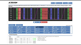
In Section 18, the emphasis is on how equipment handles voltage ripple on either AC or DC power lines. The test properly performed requires monitoring both voltage and current while ensuring that induced power doesn’t exceed 100 W. The standard calls for testing at 30 frequencies per decade with long dwell times, so automation significantly reduces operator workload. For example, Category Z ripple testing can run more than two hours per device.
Ripple can be generated directly from the signal source without using a coupling transformer, but monitoring should occur at the EUT connector for accuracy. Capacitor requirements vary and would only be used with the coupling transformer. Specifically, DC lines require a ≥100 µF capacitor from line to return, while AC lines require ≥8 µF line to neutral, and typically use a 10 µF feedthrough capacitor.
Traditional manual monitoring makes this time-consuming and error prone. AE Techron’s new automated test systems address this challenge directly, integrating voltage/current sensing and dynamic control to prevent over-testing.
AE Techron’s new Automated Level Control (ALC) technology is a closed-loop hardware/software system that dynamically measures and adjusts gain in real time. No manual tuning is required. The ALC automatically maintains amplitude across all frequency steps, preventing over-testing of your EUT.
This innovation is part of AE Techron’s CIS-25 ALC system, which integrates automation, active impedance sensing, and secondary-side voltage monitoring for accurate ripple reproduction. The result: faster, safer, and more consistent voltage ripple testing for Sections 16, 18, and 19.
Section 19: Induced Signal Susceptibility Testing
Section 19 examines how aircraft wiring and equipment respond to induced signals from nearby sources AC power lines and are coupled by magnetic and electric fields or relay chatter. Five distinct tests are outlined, including:
- Magnetic fields induced into equipment
- Electric fields induced into equipment
- Magnetic fields induced into interconnecting cables
- Electric fields induced into interconnecting cables
- Spikes induced into interconnecting cables
Test categories (A, B, C, Z) and aircraft power types (N, C, W) define exposure levels. During magnetic-field tests, cables must carry current proportional to their exposed length, so careful cable positioning and calibration are vital. Electric field tests apply high voltage to the radiating cable and should be performed with caution. The electric field into equipment test is only necessary for equipment without metal chassis. Using safety resistors and silicone-insulated wire for the electric field tests minimizes risk during high-voltage setups.
For interconnect cable testing, a 3-meter length of exposure is standard. Cables installed on aircraft, which are shorter, allow for reduced test levels, and very short cables may even qualify for exemption. Magnetic field calibration should always be done with straight wire to avoid impedance errors.
Among these tests, the chattering relay test often generates the most discussion. The goal is to simulate the transient spikes caused by a relay contact opening and closing approximately 8-10 times per second. Additionally, the chattering relay test remains unchanged in intent but will be simplified under DO-160H, which removes requirements of the specific relay type while maintaining waveform criteria.
What’s Changing in DO-160H
The upcoming DO-160H release focuses on clarity, consistency, and cleanup rather than major level changes. More than 500 change notices and 1,500 comments are being processed.
Key updates include:
- Section 16 reorganized for improved readability.
- Ground-plane and LISN requirements will be required in Sections 17-19.
- Section 15 expanded to cover both compasses and magnetometers.
- Sections 20 and 22 will have significant rewrites and updates.
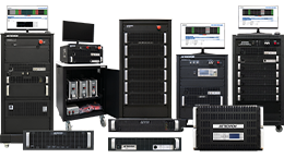
Advances in Test Solutions
AE Techron has several new systems designed to simplify and automate compliance testing:
- CIS-25 / CIS-25 ALC Systems – Preloaded waveforms and user-friendly automation for Sections 16, 18, and 19.
- DSR 400 / DSR 425 Systems – Scalable, high-current/voltage platforms with simplified setup for lab efficiency.
- HVR 1000CS System – Customizable high-voltage source for electric aircraft applications.
These innovations aim to reduce manual setup time, improve repeatability, and make high-energy tests safer for technicians and less experienced users.
Practical Tips and Takeaways
Patrick Andre closed the session with several field-tested recommendations:
- Always calibrate with NIST-traceable instruments.
- Match cable lengths to real-world installations to avoid over-testing equipment.
- Use silicone-insulated wire and high-voltage resistors of high value for electric field tests.
- Avoid impedance errors in high current tests by keeping calibration wires straight and not coiled.
- Customize test plans to reflect actual aircraft configurations rather than default templates.
Looking Ahead
With the DO-160H revision nearing completion, the aerospace community is preparing for better-defined and more efficient EMC testing. Automation, precision measurement, and smart test equipment will play key roles in meeting the growing complexity of aircraft power systems—particularly as electric propulsion and hybrid architectures emerge.