


7212
Up to 113V RMS Potential at up to 4A
7212
For Power Grid Simulation
- DC – 250 kHz bandwidth design minimizes phase shift of system output when reproducing the most rapid fault events
- Can be field-configured for high-voltage/low-current, medium voltage and current, or low-voltage/high-current applications
- Four-quadrant operation
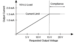
- User-selectable controlled-voltage or controlled-current modes of operation
- Protection circuitry protects from input overloads, improper output connection (including shorted and improper loads), over-temperature, over-current, and supply voltages that are too high or low
Key Performance Capabilities:
- Up to 113V RMS at up to 4A
- Pulsed output up to 30 Ap
- 430 watts RMS continuous output
- Low noise floor of only 300 µV
- Fast, 50 V/µs slew rate
- System output of over 1,700 watts is possible with multiple, interconnected amplifiers

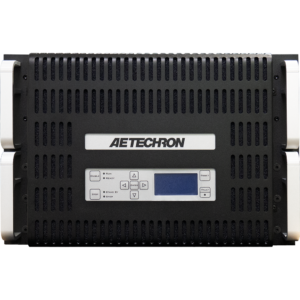
OVERVIEW
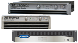
The 7212 is a four-quadrant, 0.44 kVA, DC-enabled power amplifier that was created to meet the exacting requirements of the power utility industry. It features a DC to 250 kHz bandwidth, low noise floor, fast slew rate and a 113 VRMS potential. The 7212 can be combined to form a 3-phase Y voltage source, and has a wide range of field-configurable options.
A single 7212 can output a 40 ms pulse with up to 30 amperes peak current. In continuous operation, a 7212 can provide 440 watts RMS of output power. If more voltage is needed, up to four amplifiers can be combined in series and operate as a single system.
The 7212 can operate in either voltage or current mode and can be configured by the customer for high-voltage/low-current, medium voltage and current, or low- voltage/high-current applications. It provides very low noise and fast slew rates, and can safely drive a wide range of resistive or inductive loads.
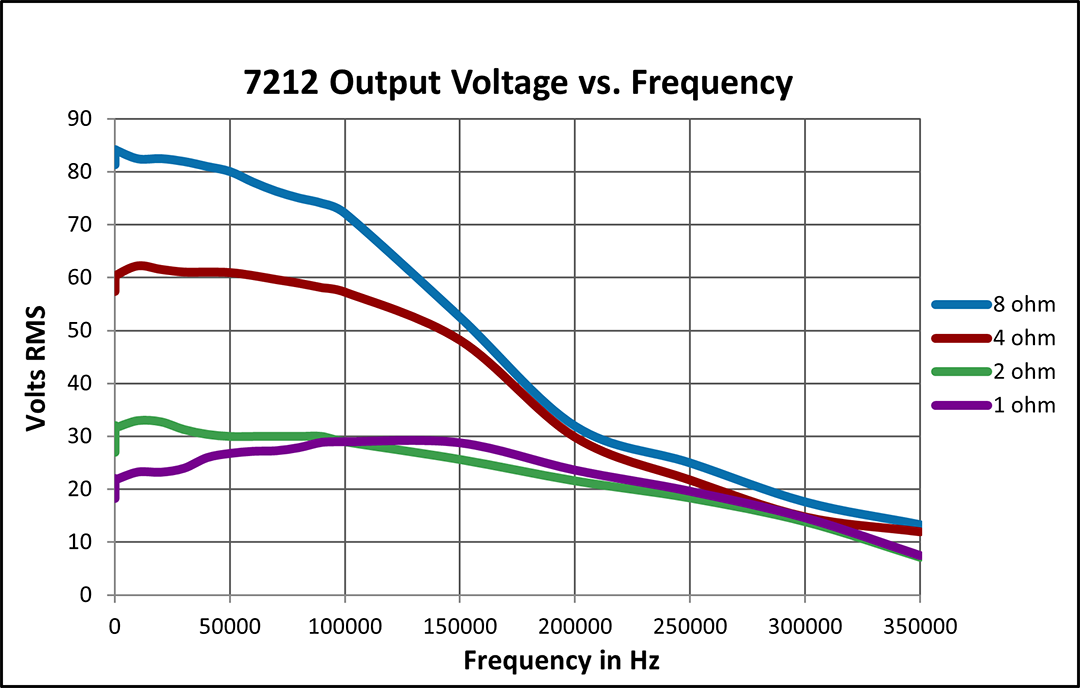
OUTPUT CHART
AC Output
Note: Testing performed into resistive loads as specified. Performance reported is typical into the specified load up to 20 kHz frequency levels. Performance may be affected when operating into highly reactive loads or above 20 kHz, reducing maximum voltage, current and power output.
*Testing not performed.
High-Voltage Mode
| PEAK OUTPUT | RMS OUTPUT | ||||||||||
| 40mSec Pulse, 30% Duty Cycle |
5 Min, 100% Duty Cycle |
1 Hr, 100% Duty Cycle |
5 Min, 100% Duty Cycle |
1 Hr, 100% Duty Cycle |
|||||||
| Ohms | Volts | Amps | Volts | Amps | Volts | Amps | Volts | Amps | Volts | Amps | Watts |
| 32 | 166 | 5.1 | 161 | 5 | 161 | 5 | 113 | 3.6 | 113 | 3.6 | 407 |
| 16 | 147 | 9 | 146 | 9 | 120 | 7.4 | 102 | 6.3 | 85 | 5.2 | 442 |
| 8 | 123 | 15 | 98 | 12 | 68 | 8.5 | 69 | 8.5 | 48 | 6 | 288 |
| 4 | 95 | 23.1 | * | * | * | * | * | * | * | * | * |
Mid-Level Mode
| PEAK OUTPUT | RMS OUTPUT | ||||||||||
| 40mSec Pulse, 30% Duty Cycle |
5 Min, 100% Duty Cycle |
1 Hr, 100% Duty Cycle |
5 Min, 100% Duty Cycle |
1 Hr, 100% Duty Cycle |
|||||||
| Ohms | Volts | Amps | Volts | Amps | Volts | Amps | Volts | Amps | Volts | Amps | Watts |
| 8 | 72 | 8.8 | 71 | 8.8 | 71 | 8.8 | 51 | 6.2 | 51 | 6.2 | 313 |
| 4 | 62 | 14.8 | 60 | 14.8 | 59 | 14.6 | 42 | 10.5 | 42 | 10.3 | 432 |
| 2 | 48 | 22.7 | 42 | 21.2 | 30 | 14.1 | 30 | 15 | 20 | 10 | 200 |
| 1 | 32 | 30 | * | * | * | * | * | * | * | * | * |
High-Current Mode
| PEAK OUTPUT | RMS OUTPUT | ||||||||||
| 40mSec Pulse, 30% Duty Cycle |
5 Min, 100% Duty Cycle |
1 Hr, 100% Duty Cycle |
5 Min, 100% Duty Cycle |
1 Hr, 100% Duty Cycle |
|||||||
| Ohms | Volts | Amps | Volts | Amps | Volts | Amps | Volts | Amps | Volts | Amps | Watts |
| 2 | 30 | 14.9 | 30 | 14.9 | 30 | 14.9 | 21 | 10.5 | 21 | 10.5 | 225 |
| 1.5 | 27 | 17.6 | 27 | 17.7 | 27 | 17.7 | 19 | 12.5 | 19 | 12.4 | 236 |
| 1 | 24 | 22.6 | 24 | 22.6 | 24 | 22.6 | 17 | 16 | 17 | 16 | 272 |
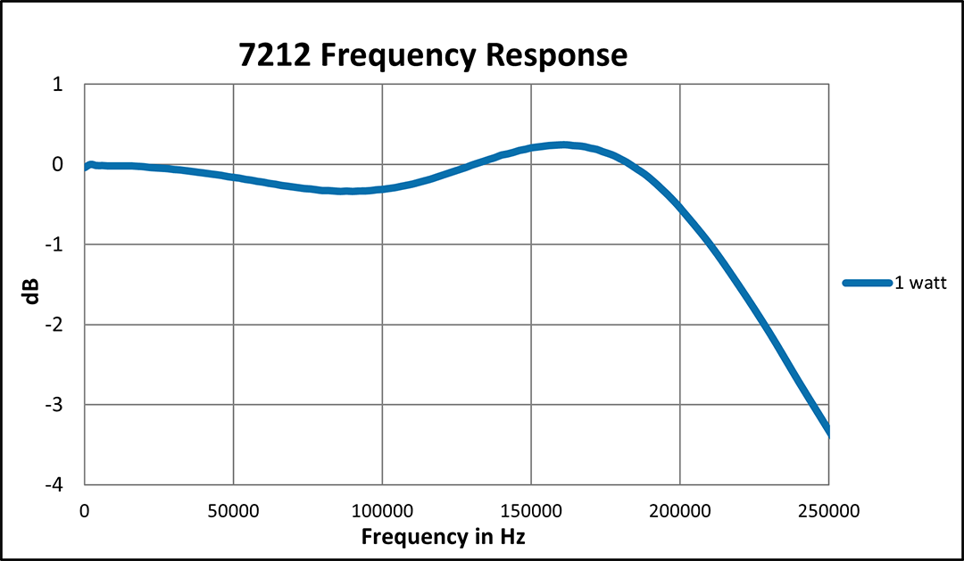
PERFORMANCE
SPECIFICATIONS
Performance
AC testing was performed at 1 kHz.
- Small Signal Frequency Response, DC – 100 kHz (1 watt): +0.0 to -3.0 dB
- 8-Ohm Power Response (continuous duty):
- DC to 60 kHz: ± 140 Vpk
- DC to 100 kHz: ± 50 Vpk
- Slew Rate: 50 V/µSec
- Residual Noise:
- 10 Hz to 300 kHz: 950 µV (0.95 mV)
- 10 Hz to 80 kHz: 300 µV (0.3 mV)
- Signal-to-Noise Ratio:
- 10 Hz – 30 kHz: –113 dB
- 10 Hz – 80 kHz: –106.6 dB
- Unit to Unit Phase Error: ±0.1 degrees at 60 Hz
- THD (DC – 30 kHz): less than 0.1%
- Output Offset: Less than ±5 mV, field adjustable to less than 1 mV
- DC Drift: ±1.5mV
- Output Impedance: 5.3 mOhm in Series with 0.95 µH
- Phase Response (10 Hz – 10 kHz) : ±5 degrees plus 560 nsec propagation delay
Input Characteristics
- Balanced with ground: Three terminal barrier block connector, 20k ohm differential
- Unbalanced: BNC connector, 10k ohm single ended.
- Gain (variable or fixed),
- Voltage Mode: 20 volts/volt
- Current Mode: 5 amperes/volt
- Max Input Voltage: ±10V, balanced or unbalanced
- Input Impedance: 20k ohm differential
- Common Mode Rejection: -58 dB with 5V input
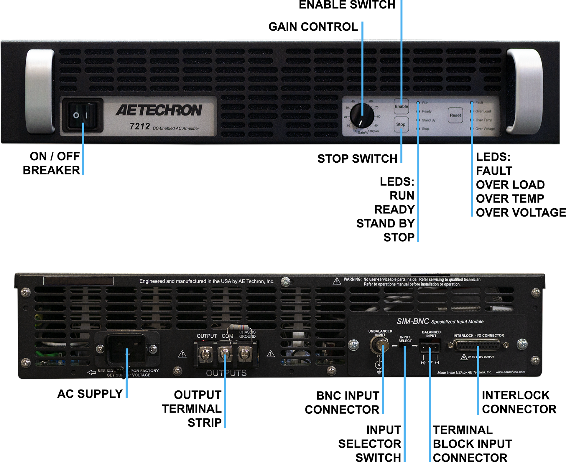
Status Display, Control, I/O
- Front Panel LED Displays indicate: Ready, Standby, Fault, Over Temp, Over Voltage, Overload
- Soft Touch Switches for: Run, Stop, Reset
- Gain Control, when enabled: Voltage gain adjustable from 20 to 0
- On/Off Breaker
- Back Panel Power Connection: 25 Amp IEC (with retention latch)
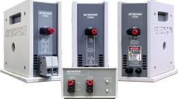
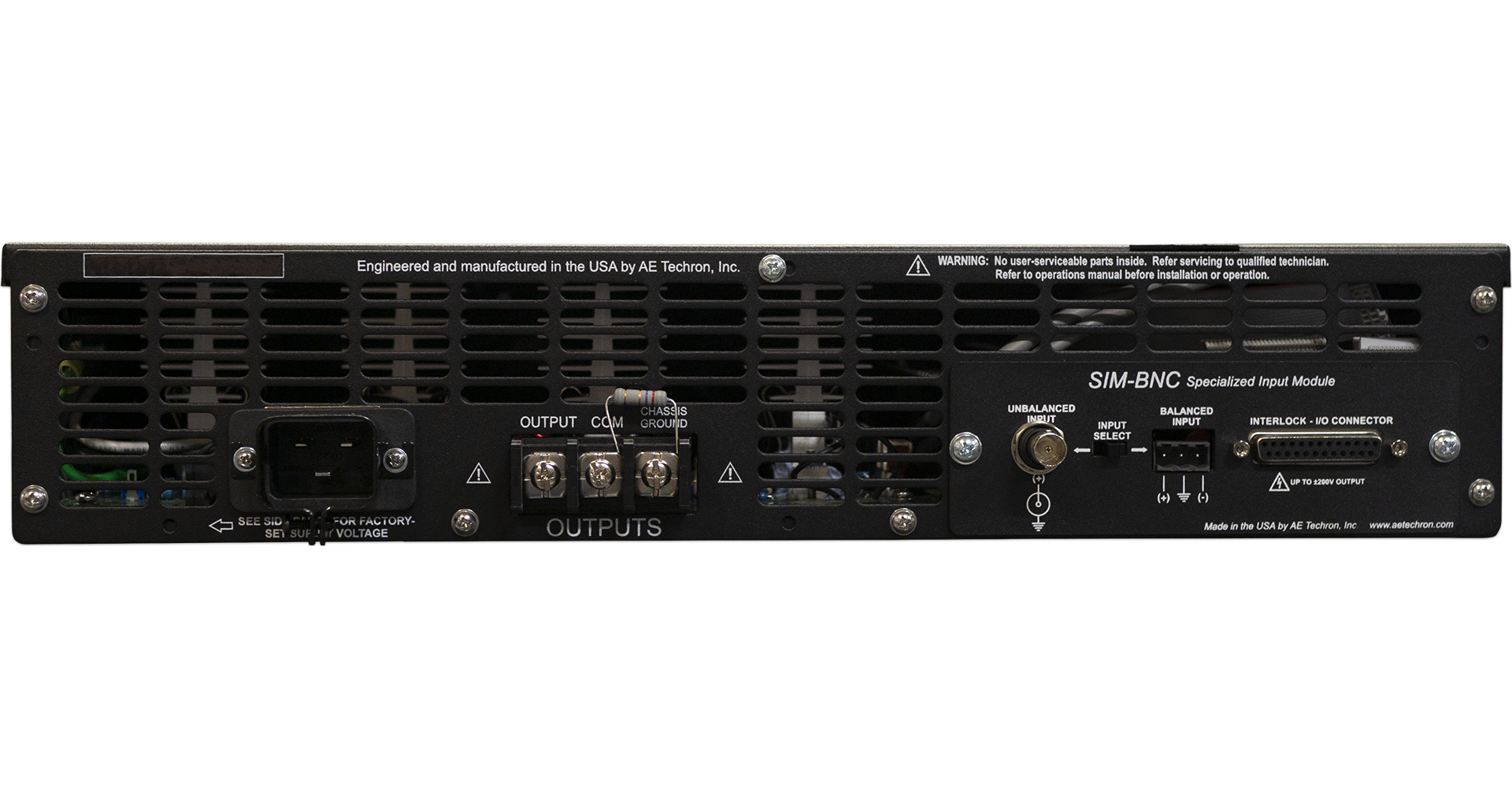
- Signal Output: Three-position terminal strip (OUTPUT/COM/CHASSIS GROUND)
- Signal Input: User Selectable BNC or Barrier Strip, Balanced or Unbalanced
Communication Capabilities
- Current Monitor: 5A/V ± 1%; 2.5A/V ± 1% (differential configuration)
- Reporting: System Fault, Over Temp, Over Voltage, Over Load
- Remote Control via Interlock Connector: Force to Standby, Reset after a fault
Protection
- Over/Under Voltage: ± 10% from specified supply voltage amplifier is forced to Standby
- Over Current: Breaker protection on both main power and low voltage supplies
- Over Temperature: Separate Output transistor, heat sink, and transformer temperature monitoring and protection
Physical Characteristics
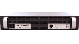
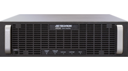
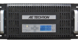
- Chassis: The Amplifier is designed for stand- alone or rack-mounted operation. The Chassis is black aluminum with a powder coat finish. The unit occupies two EIA 19-inch-wide units.
- Weight: 35 lbs (15.9 kg), Shipping 45 lbs (20.4 kg)
- AC Power: Single phase, 120 VAC, 60 Hz, 10 Amp service; (220-240 VAC, 50-60 Hz, 5 Amp service model available)
- Operating Temperature: 10°C to 50°C (50°F to 122°F), maximum output Power de-rated above 30°C (86°F).
- Humidity: 70% or less, non-condensing
- Cooling: Forced air cooling from front to back through removable filters.
- Airflow: 180CFM
- Dimensions (HxWxD): 3.5” x 19” x 22.75” (8.9 cm x 48.3 cm x 57.8 cm)
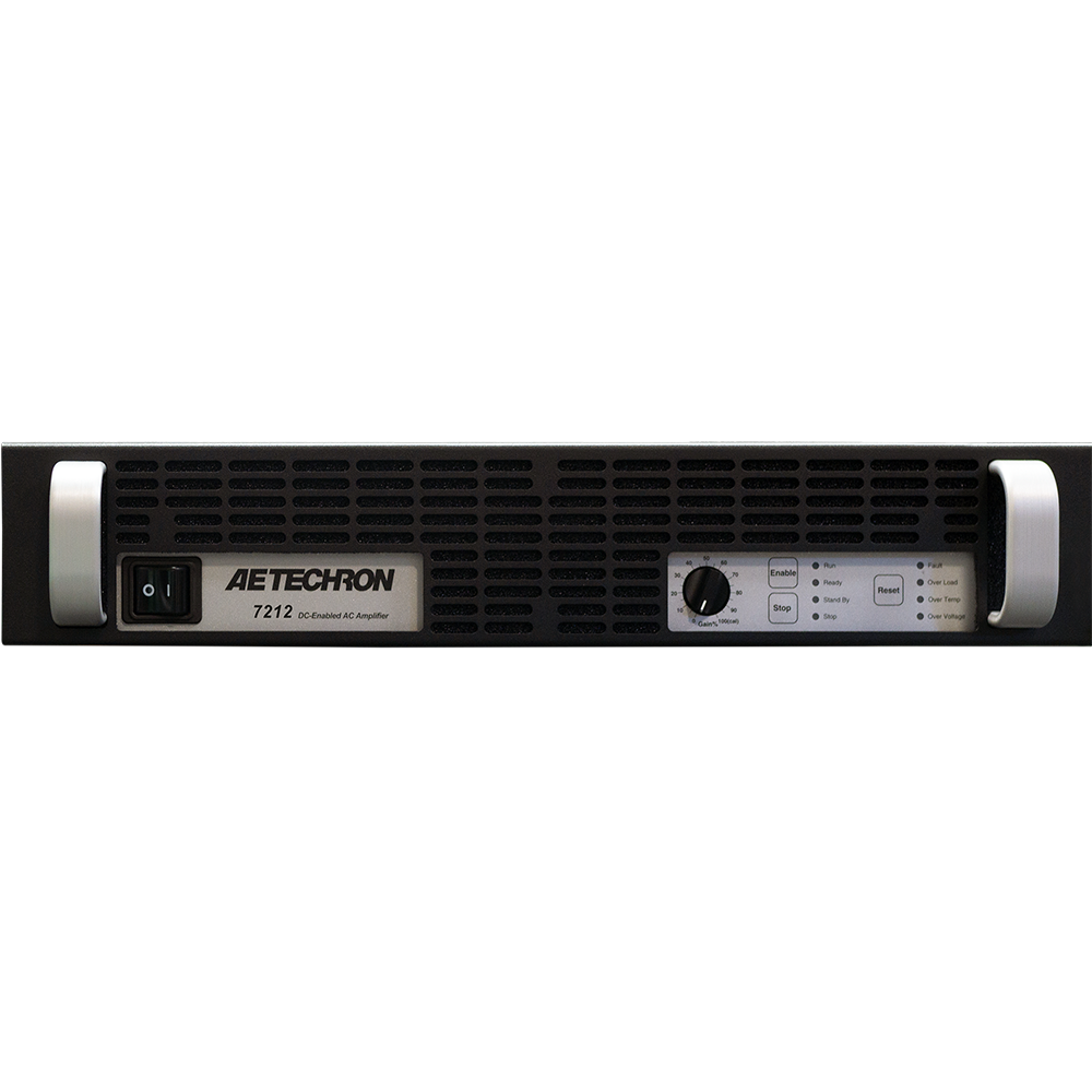
PHOTOS
Controls, Indicators and Connectors
DOCUMENTS / DOWNLOADS
| 7212 Data Sheet | 7212 Manual | SIM Interlock Connector Pinouts and Functions | Configuration Settings | Step File for Chassis |
 |
 |