In high-power electrical test environments, understanding the differences between real power and apparent power is critical for system design and equipment selection. This distinction becomes especially important when choosing the right power amplifier for your application – whether you’re powering a resistive load under steady-state conditions or stress-testing an aircraft subsystem with complex transient waveforms.
Real Power vs. Apparent Power: Key Concepts
- Real Power (P): Measured in watts (W), it represents actual work performed by the system. Applies to purely resistive loads where voltage and current are in phase.
- Apparent Power (S): Measured in volt-amperes (VA), it represents the total power delivered to a load, including reactive power. Applies to reactive or inductive loads.
- Power Factor (PF): Defined as P/S (real/apparent). Values range from 0 (purely reactive) to 1 (purely resistive).
In AC power systems, especially in test and simulation environments, understanding the distinction between real, reactive, and apparent power is critical to correctly sizing equipment and predicting system behavior.
Real Power (P) – “Watts”
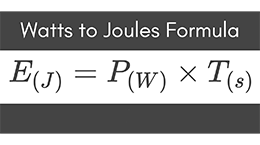
Real power, measured in watts (W), is the actual power consumed by a load to perform useful work—such as generating heat, light, or mechanical motion. It’s calculated as:
P = V × I × cos(θ)
- V = RMS voltage
- I = RMS current
- θ = phase angle between voltage and current
In purely resistive loads (like heaters or incandescent lamps), voltage and current are in phase, so cos(θ) = 1, and real power = apparent power.
Reactive Power (Q) – “VAR”
Reactive power, measured in volt-amperes reactive (VAR), does not perform any real work but is essential to sustaining electric and magnetic fields in inductive or capacitive components—such as motors, coils, transformers, or power supplies.
Q = V × I × sin(θ)
Reactive power flows back and forth between the source and the load, increasing the current demand and resulting in higher conductor losses and component stress without delivering additional real energy.
Apparent Power (S) – “VA”
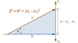
Apparent power, measured in volt-amperes (VA), is the vector sum of real and reactive power. It represents the total power capacity the amplifier must supply to drive the load.
S = V × I = √(P² + Q²)
This value determines the thermal and electrical sizing of amplifiers, transformers, and conductors. Even if a load consumes very little real power, a poor power factor (e.g., <0.7) can cause S to be large, requiring an amplifier with significantly more headroom.
Power Factor (PF)
The power factor is the ratio of real power to apparent power:
PF = cos(θ) = P / S
- PF = 1.0: Ideal (resistive load only)
- PF < 1.0: Load includes reactive elements (inductive or capacitive)
- PF = 0.0: Purely reactive load (no real work done)
An amplifier driving a load with PF = 0.5 must process twice the apparent power compared to the real power consumed. This is critical in test scenarios with rapidly changing waveforms or loads that include inductors, capacitors, or switching converters.
Power Triangle: Real, Reactive, and Apparent Power

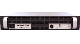
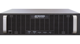
The 8500 Series: Optimized for Apparent Power Dominant Applications
The 8500 Series delivers exceptional performance for applications involving high apparent power – common in reactive or nonlinear test environments. Its ability to provide up to 5x rated power in apparent power makes it ideal for stress testing and transient simulation.
Key Features
- Bandwidth: DC to 50 kHz
- Apparent Power Handling: Up to 5x continuous power
- Surge Capability: Up to 20 kW
- Load Compatibility: Best suited for reactive loads
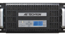
The 8600 Series: Engineered for Real Power Efficiency
The 8600 Series delivers strong performance in real power applications. Its higher power factor (0.97) and efficiency (89%) make it well-suited for steady-state and resistive loads.
Key Features
- Bandwidth: DC to 50 kHz
- Apparent Power Handling: Up to 2x continuous power
- Surge Capability: Up to 20 kW
- Load Compatibility: Best suited for resistive loads
Choosing the Right Amplifier: Application Scenarios

Conclusion
Understanding the distinctions between real and apparent power is key to optimizing test setups and ensuring amplifier longevity and performance. AE Techron’s 8500 Series and 8600 Series amplifiers each offer compelling advantages depending on the dominant power demand.
- Use the 8500 Series when your application demands flexibility across wide power factors, reactive loads, and transients.
- Choose the 8600 Series when energy efficiency, real power fidelity, and compact design are top priorities.
For help determining the best model for your specific application, contact AE Techron technical sales support.