



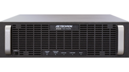






















7796RLY
Up to 200 Ap Current Source

7796RLY
For Protection Relay Production Testing and Commissioning
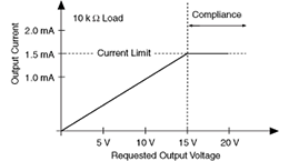
- High compliance voltage allows the 7796RLY to drive electromechanical relays directly
- Maintains phase accuracy for any load from a dead short to 0.25 ohms
- Front panel indicators for rapid assessment of amplifier status
- Protection circuitry protects from input overloads, improper output connection (including shorted and improper loads), over-temperature, over-current, and supply voltages that are too high or low
Key Performance Capabilities:
- Up to 200 Ap (141A RMS) output power at 0.5 ohms
- Up to 183 Vp output voltage
- Standard transconductance of 20 ±0.2% from short to 1-ohm load
- Residual noise of less than 2.5 mA peak, from 40 Hz to 600 Hz

OVERVIEW
The 7796RLYwas created to meet the demanding requirements of the power utility industry. Capable of outputting up to 200 amperes peak current, the 7796RLY is powerful enough to put protection relays, fuses and other critical components through a full range of tests.
It is capable of a controlled-voltage bandwidth of DC – 100 kHz and a controlled-current bandwidth of DC – 10 kHz. The low noise floor, low distortion and minimal phase error of the 7796RLY make it the ideal amplifier for power grid modeling.
OUTPUT CHART
Pulse/Burst Specifications
| TOTAL LOAD | DURATION | WAVEFORM | OUTPUT POWER |
| 0.19 ohms | 1 minute | 60 Hz Sine | 125A RMS / 176A peak |
| DC | 60A peak | ||
| 0.5 seconds | 60 Hz Sine | 141A RMS / 200A peak | |
| DC | 188A peak | ||
| 0.2 seconds | 60 Hz Sine | 141A RMS / 20A peak | |
| DC | 188A peak | ||
| 0.53 ohms | 1 minute | 60 Hz Sine | 91A RMS / 128A peak |
| DC | 100A peak | ||
| 0.5 seconds | 60 Hz Sine | 137A RMS / 193A peak | |
| DC | 164A peak | ||
| 0.2 seconds | 60 Hz Sine | 139A RMS / 196A peak | |
| DC | 164A peak | ||
| 1.07 ohms | 1 minute | 60 Hz Sine | 75A RMS / 107A peak |
| DC | 66A peak | ||
| 0.5 seconds | 60 Hz Sine | 83A RMS / 118A peak | |
| DC | 108A peak | ||
| 0.2 seconds | 60 Hz Sine | 85A RMS / 120A peak | |
| DC | 108A peak |
Accuracy
| Amplitude vs Frequency at 1V input, 20A output, amplifier transconductance set to 20 |
|||
| Load | Input Signal | Transconductance | |
| 1 kHz | 100 Hz | ||
| 2 Ω | Sine | 19.9 | 20 |
| 1 Ω | Sine | 20 | 20 |
| o.5 Ω | Sine | 20 | 20 |
| Short* | Sine | 20 | 20 |
* Unimpeded wire.
SPECIFICATIONS
Performance
- Controlled-Current Bandwidth (0.25-ohm load): DC to 10 kHz
- Maximum Output Current (0.19-ohm load): 141A RMS (200 Ap)
- Maximum Output Voltage: 183 Vp
- Maximum Output Power:: Dependent on load and frequency
- Load Constraint for Maximum Output: 0.19 ohms + 200 mH
- Output Offset Current: Less than 10.0 mA DC peak
- Standard Transconductance (from short to 1-ohm load): 20 ±0.2%
- Unit-to-Unit Phase Error (60 Hz): ±0.1 degrees
- Residual Noise (40 to 600 Hz): Less than 2.5 mA peak
- THD + Noise (600 Hz at full output power):: Less than 0.10%
Input Characteristics
- Balanced with ground: Three terminal barrier block connector, 20k ohm differential
- Unbalanced: BNC connector, 10k ohm single ended.
- Max Input Voltage: ±10V, balanced or unbalanced
- Common Mode Rejection(40 to 600 Hz): -58 dB minimum
Status Display, Control, I/O
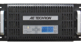
- Front Panel LED Displays indicate: Ready, Standby, Stop, and Fault conditions in the output stage
- LCD Display: User-configurable for up to four simultaneous displays reporting one, two, or all four of the following: Voltage Peak, Voltage RMS, Current Peak, and Current RMS. If an amplifier fault condition occurs, the front panel display lists the type of fault condition and gives suggested corrective action.
- Soft Touch Switches for: Run, Stop, Reset
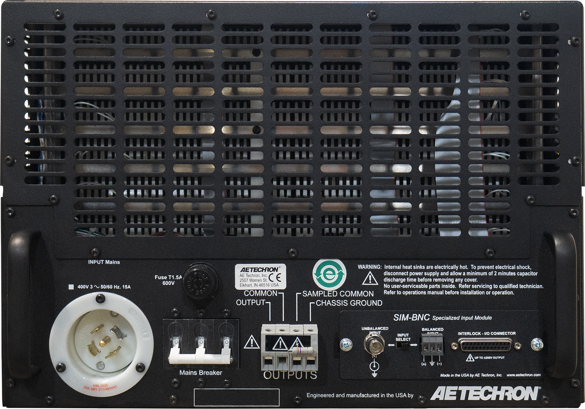
- Back Panel Power Connection:NEMA-style locking receptacle; matching AC connector also included
- Signal Output: Four-position barrier block (OUTPUT/COMMON/SAMPLED COMMON/CHASSIS GROUND)
- Signal Input: User Selectable BNC or Barrier Strip, Balanced or Unbalanced
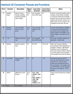
- Interlock Connector: 25-pin D-sub connector used for amplifier control and status applications; also used in multi-amplifier applications
Communication Capabilities
- Current Monitor: 20A/V ± 1%; 10A/V ± 1% (differential configuration)
- Reporting: System Fault, Over Temp, Over Voltage, Over Load
- Remote Control via Interlock Connector: Blanking control, Force to Standby, Reset after a fault
Protection
- Over/Under Voltage: ± 10% from specified supply voltage amplifier is forced to Standby
- Over Current: Breaker protection on both main power and low voltage supplies
- Over Temperature: Separate output transistor, heat sink, and transformer temperature monitoring and protection
Physical Characteristics
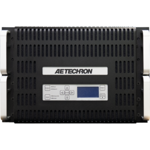
- Chassis: Black powder-coat chassis with all aluminum construction; designed for stand-alone or rack-mounted operation. The amplifier occupies seven EIA 19-inch-wide rack units
- Weight: 110 lbs (50 kg)
- AC Power: Three-phase, 208 VAC ±10%, 47-60 Hz, 20A AC service (400 VAC ±10%, 15A version available). A toggle switch circuit breaker opens all legs of the AC mains on excess current demand.
- Operating Temperature:
10°C to 50°C (50°F to 122°F), maximum output Power de-rated above 30°C (86°F). - Humidity: 70% or less, non-condensing
- Cooling: Forced-air cooling from front to back through removable filters via four 100 ft3/min. fans. No space is required between rackmounted amplifiers. Air filters are removable from the rear via one fastener per side and may be eliminated if cabinet filtration is provided.
- Dimensions (HxWxD): 12.75” x 19” x 22.8” (31.3 cm x 48.3 cm x 57.9 cm)
PHOTOS
Controls, Indicators and Connectors

DOCUMENTS / DOWNLOADS
| 7796RLY Data Sheet | 7796 Manual | 7796RLY Manual Supplement | SIM Interlock Connector Pinouts and Functions | DXF Model for Chassis | Step File for Chassis |
 |
 |
 |
 |
 |
 |