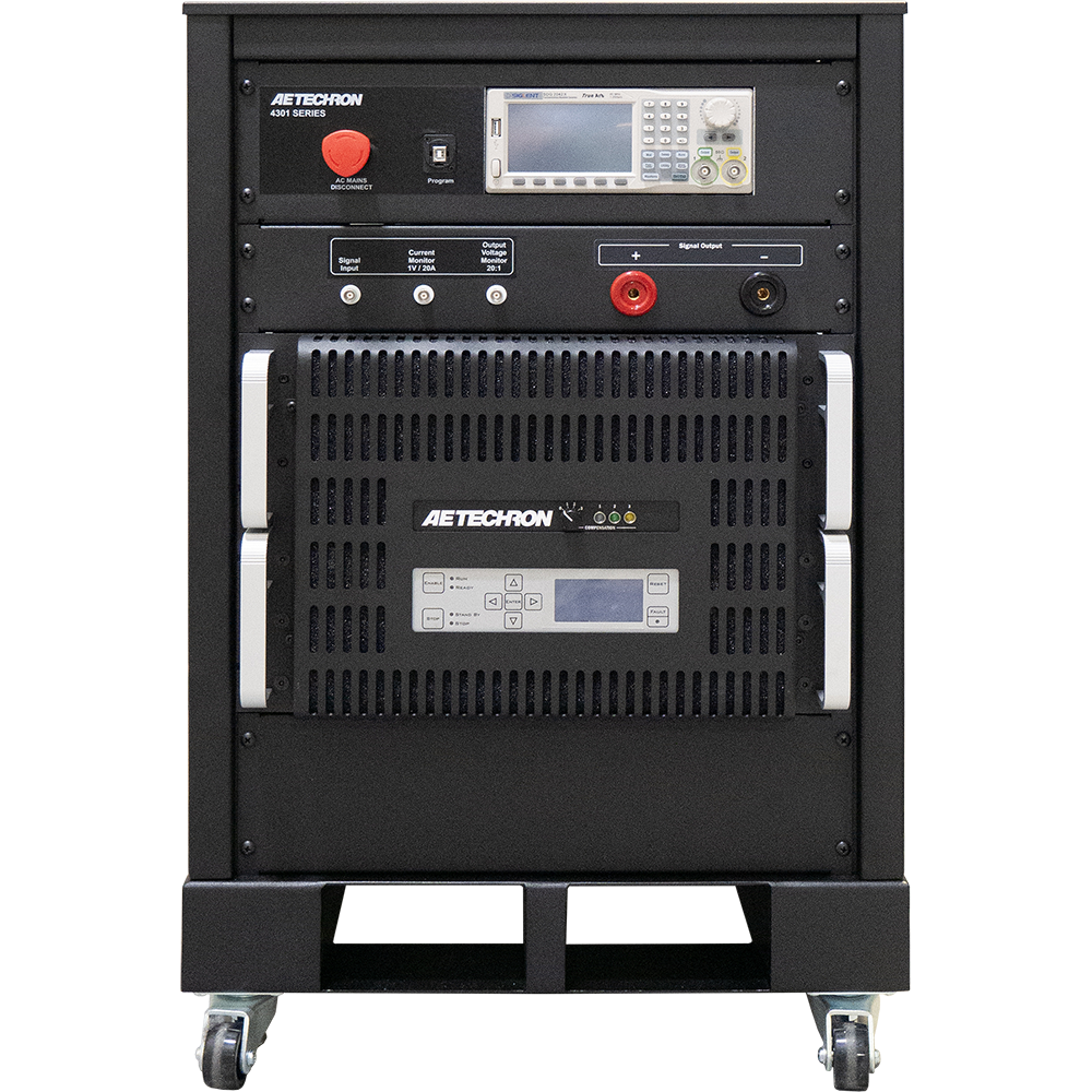
4301 Series

DC Voltage Variations and Telecom Transients Testing

4301 Series

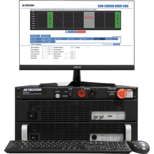
The 4301 Series Telecom Test Systems have been specially designed for EMC testing of network telecommunications equipment and are the best systems available for producing the waveforms required for transient voltage measurements as described in GR-1089 Section 10 and ATIS-0600315.2007.

Key Performance Capabilities:

  • Slew rates up to 60 V/µsec.
  • Up to 240A DC at +50VDC or –50VDC (4301-240 configuration).
  • Can provide pulses of up to 800 amps at voltages of up to ±100V (4301-240 configuration).
  • Adjustable compensation allows the system to maintain a 50V/2 µsec rise-time over a wide range of current outputs.


SKU: N/A Category:
OVERVIEW

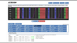
The 4301 includes a SDG2042X Function/Arbitrary Waveform Generator, which comes pre-programmed and integrated into the 4301 system. Together, the 4301 with Siglent AWG provide a complete solution for GR-1089 Section 10/ATIS-0600315.2007 testing.

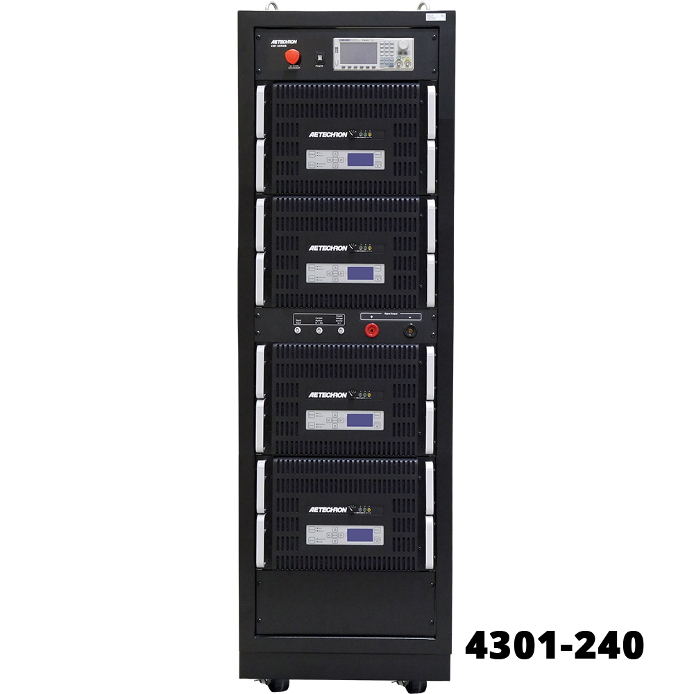
The 4301 system is available in four standard configurations and is capable of slew rates of up to 60 V/µsec. In its largest configuration (model 4301-240), the 4301 system can provide up to 240A of DC at ±50VDC and can provide pulses of up to 800 amps at voltages of up to ±100V. The system has a voltage gain of 20 and can accept input voltages of up to ±10V.

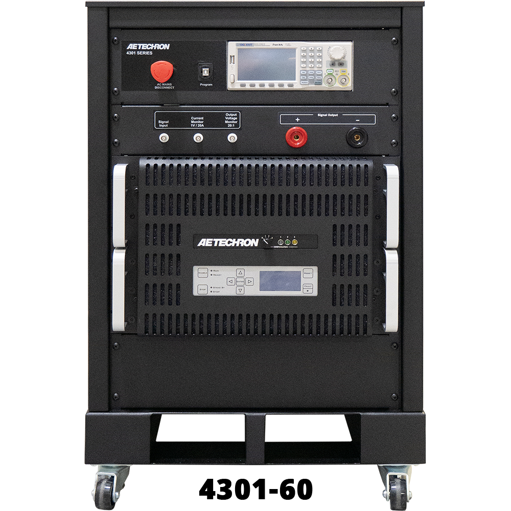
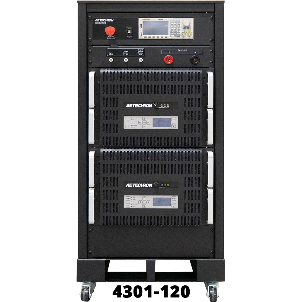
Lower power versions of the 4301 amplifier solution are available for users with lower current requirements: 4301-180 (180A), 4301-120 (120A) and 4301-60 (60A).


Telecom Test Systems

  • Complete solution for GR-1089 Section 10 and ATIS-0600315.2007 DC Voltage Variations and Transients Testing
  • Siglent SDG2042X Function/Arbitrary Waveform Generator comes pre-programmed and integrated into the 4301 system
  • Four selectable compensation settings
 
SPECIFICATIONS

Indicators and Controls

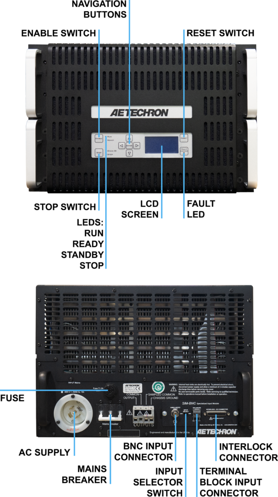
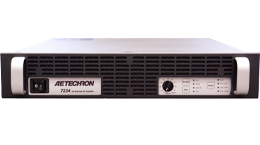
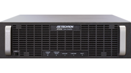
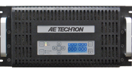
The unit’s indicators and controls are located on the 4301 amplifier modules. The 4301 models contain between one and four amplifier modules.

  • LED Displays: Indicators for Run, Ready, Standby, and Stop status, and Fault conditions in the output stage.
  • LCD Display: Can be user-configured for up to four simultaneous displays reporting one, two, or all four of the following: Voltage Peak, Voltage RMS, Current Peak and Current RMS. When the amplifier module is in a Fault condition, the LCD Display lists the type of fault condition and gives suggested corrective action.
  • Navigation Buttons: The Navigation Buttons provide four arrow keys to allow navigation through the various LCD display options.
  • Soft Touch Switches: Soft touch switches allow the selection of Run (Enable), Stop and Reset functions.
  • Compensation Setting: A four-position rotary control allows the selection of optimum compensation settings according to the total current required at the system output.
  • Compensation LEDs: When the amplifier module is receiving AC power, the colored LED associated with the selected Compensation setting will be lit.
 

Inputs and Outputs

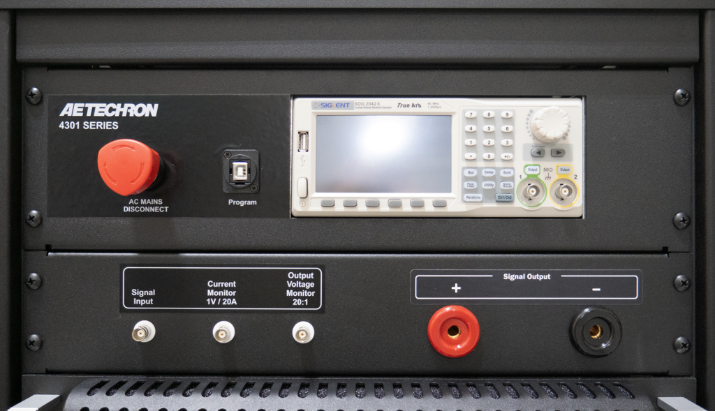
The unit’s inputs and outputs are located on the cabinet’s front panel.

  • Signal Input: A BNC connector accepts input from an arbitrary waveform generator.
  • External Trigger Output: A BNC connector provides the signal to the Trigger In connector on the AWG.
  • Current Monitor Output: A BNC connector provides scaled voltage output for current monitoring.
  • Voltage Monitor Output: A BNC connector provides scaled voltage output for voltage monitoring.
  • Signal Output: 250A Pin Plug connectors (or optional Anderson SB350 connectors) provide signal output to the equipment under test.
  • AWG: A Siglent SDG2042X Function/Arbitrary Waveform Generator is integrated into the 4301 system. The AWG comes pre-programmed with the required test waveforms and is mounted securely within the 4301 cabinet. A GPIB port located next to the AWG on the system front panel allows communication with the AWG through a user-supplied computer.
 

Options

SB350 Outputs Option: Anderson SB350 output connectors can be substituted for the standard 250A Pin Plug connectors.


Protection

  • Fault: The Fault LED on an amplifier module will light and the error message “Warning! Output Device Fault” will be displayed on the LCD screen if the module’s output stage stops operating. If this happens, contact AE TECHRON for servicing information.
  • AC Under/Over Voltage Protection: If the AC line voltage rises or drops more than10% of the nominal operating voltage, the system will be forced to Standby and the error message “Warning! Overvoltage” will be displayed on the LCD screen of the amplifier module(s).
  • Over Current: Each amplifier module contains breaker protection on both the unit’s main power supply and the low-voltage supplies. The 4301 system provides a Main Power breaker switch and an Auxiliary Power breaker switch located inside the cabinet rear door.
  • Over Temperature: Each amplifier module contains separate output transistor, heat-sink and transformer temperature monitoring and protection circuits.
 

Physical Characteristics

  • Cabinet: Welded steel cabinet with a textured black, powder-coat finish.
  • Main Power: A main power selector located on the system front panel controls the main power supply to the system.
  • Operating Temperature: 10°C to 50°C (50°F to 122°F), Maximum Output Power de-rated above 30°C (86°F).)
  • Humidity: 70% or less, non-condensing.
  • Cooling: The 4301 system amplifier modules employ forced air-cooling from front to back through removable filters via six 100 ft3/min. fans per unit. No space is required between rack-mounted modules. Provide room at the cabinet back to allow for proper airflow.
MODEL COMPARISON
Model 4301-60 4301-120 4301-180 4301-240
Max. Continuous DC Current (±50 VDC) 60A 120A 180A 240A
Max. Pulse DC Current (up to ±100VDC) 200A 400A 600A 800A
Voltage Gain 20 20 20 20
Maximum Input Voltage ±10V, unbalanced ±10V, unbalanced ±10V, unbalanced ±10V, unbalanced
Compensation Setting (for current required at system output) Setting 0 off: 0 to 6A
Setting 1: 6 to 12A
Setting 2: 12 to 50A
Setting 3: 50 to 60A
Setting 0 off: 0 to 12A
Setting 1: 12 to 24A
Setting 2: 24 to 100A
Setting 3: 100 to 120A
Setting 0 off: 0 to 18A
Setting 1: 18 to 36A
Setting 2: 36 to 150A
Setting 3: 150 to 180A
Setting 0 off: 0 to 24A
Setting 1: 24 to 50A
Setting 2: 50 to 200A
Setting 3: 200 to 240A
Current Monitor Output
(= 1V monitor output)
20A output 40A output 60A output 80A output
Voltage Monitor Output
(= 1V monitor output)
20A output 10A output 10A output 10A output
Required AC Mains, three-phase, 47-60 Hz, five-conductor wiring (±10%) 208 VAC: 30A AC service
400 VAC: 15A AC service
208 VAC: 60A AC service
400 VAC: 30A AC service
208 VAC: 90A AC service
400 VAC: 45A AC service
208 VAC: 120A AC service
400 VAC: 60A AC service
Dimensions (HxWxD) 27 x 34 x 22.5 in
68.6 x 86.4 x 57.2 cm
52 x 22 x 31.5 in
132 x 55.9 x 80 cm
74 x 22 x 31.5 in
188 x 55.9 x 80 cm
74 x 22 x 31.5 in
188 x 55.9 x 80 cm
Net Weight (approx) 307 lbs (139 kg) 454 lbs. (206 kg) 697 lbs. (316 kg) 850 lbs. (386 kg)
Shipping Weight (approx) 458 lbs (208 kg) 589 lbs. (267 kg) 897 lbs. (407 kg) 1,050 lbs. (476 kg)
PHOTOS

Amplifier Module Front & Back

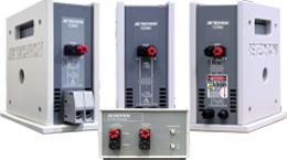
Cabinet Panels

DOCUMENTS / DOWNLOADS
4301 Series Datasheet 4301 Series Operator’s Manual


Need to Meet a Test Standard?
Search the AE Techron standards database to find the amplifier or test system to fit your testing requirements.


Looking for a Specific Test Standard?
Review the AE Techron standards database to determine if it contains the specific tests you need to perform.

Test Standards Selector

Test Standards Library


EMC

We provide comprehensive solutions for power quality, conducted immunity, and induced susceptibility testing for the EMC industry.


IMAGING
Low-noise power amplifiers are a necessary piece of equipment for imaging technologies used in various industrial and research applications, such as small-bore and low-field MRI, MPI, and NMR.


ENERGY SECTOR

We designed a range of amplifiers and testing equipment to meet the demanding requirements of the power utility industry and energy sector. With output up to 200 amperes peak current, our relay testing amplifiers are powerful enough to put protection relays, fuses and other critical components through a full range of tests.


RESEARCH

AE Techron’s family of amplifiers and EMC test systems are used in a variety of industrial and academic research settings. 

EMC
Automotive
Aviation
Capacitor
Military
Telecom

ENERGY SECTOR
Relay Testing
Power Grid Simulation
Microgrid Testing
Power HIL

IMAGING
MRI
NMR
MPI
Low-field

RESEARCH
Magnetic Field Generation
Real-Time Simulations
High-Performance Amplification
EMC Testing
Emerging Technologies


Linear Amplifiers
Our linear amplifiers offer DC-1MHz with fast rise times and a very low noise floor. They are excellent at driving resistive loads and are used in for various applications in research, university labs, EMC, imaging, and magnetics.


Switch-mode Amplifiers
Our switch-mode amplifiers have the lowest noise floor on the market, while providing high bandwidth at a very low cost per watt. They are excellent at driving inductive and capacitive loads, reusing the returned power to increase apparent power as much as 4X greater than the rated power.


Gradient Amplifiers 
AE Techron is an industry pioneer in MRI. Our gradient amplifiers are high-power, DC-enabled linear amplifiers with an integrated power supply. They offer a wide bandwidth, very low noise, and exceptional control of drift and distortion.


Looking for a particular amplifier?
Search the AE Techron product database to find the amplifier to fit your specific needs.


RLY Amplifiers
Our RLY amplifiers are created to meet the demanding requirements of the power utility industry. With models capable of outputting up to 200 amperes peak current, these amplifiers are powerful enough to put protection relays, fuses and other critical components through a full range of tests. Low noise floor, low distortion and minimal phase error make these amplifiers ideal for power grid modeling.


EMC Test Systems
We provide comprehensive solutions for power quality, conducted immunity, and induced susceptibility testing for the EMC industry.


Other Products from AE Techron
We produce a wide range of products that meet the requirements for specific standards testing. From a chattering relay to three different coupling transformers, we offer solutions for you to build your own custom test system.


Need an accessory to go with your amplifier?
Choose from our list of amplifier accessories, including cables and wiring kits.


Legacy Products
Check out our library of datasheets for amplifier models no longer in production.

GRADIENT AMPLIFIERS
7000g Series / 50A - 200A

RLY AMPLIFIERS
Voltage Amp / 150A
Current Amps / 5A - 200A


AE Techron Service
Our Technical Support and Service Center provides an easy 3-step service process, if you are having issues with one of our products.


Crown & JBL Service
AE Techron has been repairing Crown amplifiers, old and new, since 1999. From D75s to the latest powered speaker amplifier modules, our repair technicians have 70+ years of combined experience repairing Crown amplifiers and JBL Pro amplifier modules.


Crown Museum Tour
Enjoy a video tour of the Crown Audio Museum, presented by Gerald Stanley


Support Articles
We offer tech notes, white papers, field service guides, and an FAQ to help you diagnose any issues you may be having with a product.


Warranty Information
Read the details of AE Techron’s 3-year, no-fault warranty guarantee.


Authorized Service Centers
Local access to approved service centers for AE Techron products is facilitated through a network of trained representatives, each with a minimum standard repair capability.


Thank you for your repair order!
Your satisfaction is our top priority and your opinion matters to us. Please complete this short satisfaction survey and tell us more about your experience.


Authorized Service Centers Only
This link takes our Authorized Service Centers to a resource page that provides instructional videos and manuals for the service and repair of AE Techron products.

AE Techron Service

Crown & JBL Service

Crown Museum Tour

Support Articles

Warranty Information

Authorized Service Centers

Service Satisfaction Survey

Service Resources (restricted)


Experience the AE Techron Story
AE Techron is a recognized world leader in the design and manufacture of precision, audio-frequency industrial power amplifiers and EMC product safety compliance test systems. But there is more to our company than just our amplifiers and test systems.


Join us at an upcoming event
Check out the schedule of regional, national, and international trade shows that we are participating in this year.


Join a company who cares about your opinion and future
Searching for a new challenge with an innovative forward-thinking company? Explore our latest career opportunities.


Visit the AETech Blog
Explore our blog postings to learn more about our products and the industries we serve.


News and Announcements
Updates on AE Techron products, our sales partners, and the industry we serve.


Thank you for choosing AE Techron
Your satisfaction is our top priority and your opinion matters to us. Please complete this short satisfaction survey and tell us more about your experience.

About AE Techron

Event Calendar

Careers

AE Tech Blog

News & Announcements

Customer Satisfaction Survey

Conversion Calculators
Formulas, equations, and calculation tools for most compliance engineering applications.


Ohm’s Law
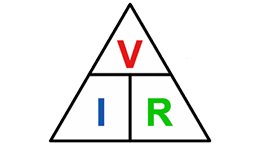
Ohm's Law is valid for circuits that contain only resistive elements (no capacitors or inductors). Ohm's Law is true for voltage and current (DC) or (AC).


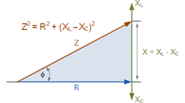
Effective Impedance
Effective Impedance is the DC resistance plus the additional apparent impedance caused by inductance and capacitance at a specified frequency.


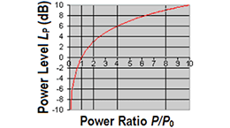
Voltage to dB Converter
This function converts the linear relationship between two voltages or powers into decibels, and decibels in power or voltage gain or attenuation.


Voltage Dropped & Power Dissipated Across a Series Resistor
Power dissipation is a measure of how much power is converted into heat in a circuit due to inefficiencies.


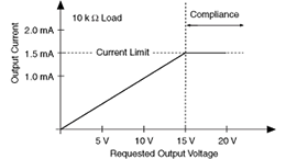
Compliance Voltage
Compliance voltage represents the maximum voltage a current source will reach as it attempts to produce the desired current at the desired rate of change.


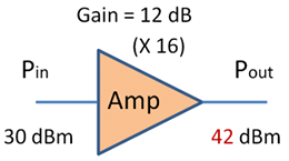
Decibel Conversion
Converts between decibels, voltage (or current) gain, and power gain.


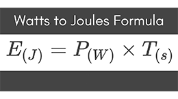
Watts to Joules Conversion
Convert watts to joules by entering the power in watts and time in seconds using this easy calculator.


Contact AE Techron
Use this form or provided phone numbers to contact our home office, sales, service, or technical support.


Find a Sales Partner
Our Sales Partners are independent resellers who represent AE Techron products. They are very knowledgeable about AE Techron products and the industries that they service.


Exclusive Rental Partner
Advanced Test Equipment Corp. is the exclusive world-wide Rental Partner for AE Techron. They are extremely knowledgeable about AE Techron products and the industries that they service.

Contact Us

Sales Partners

Exclusive Rental Partner