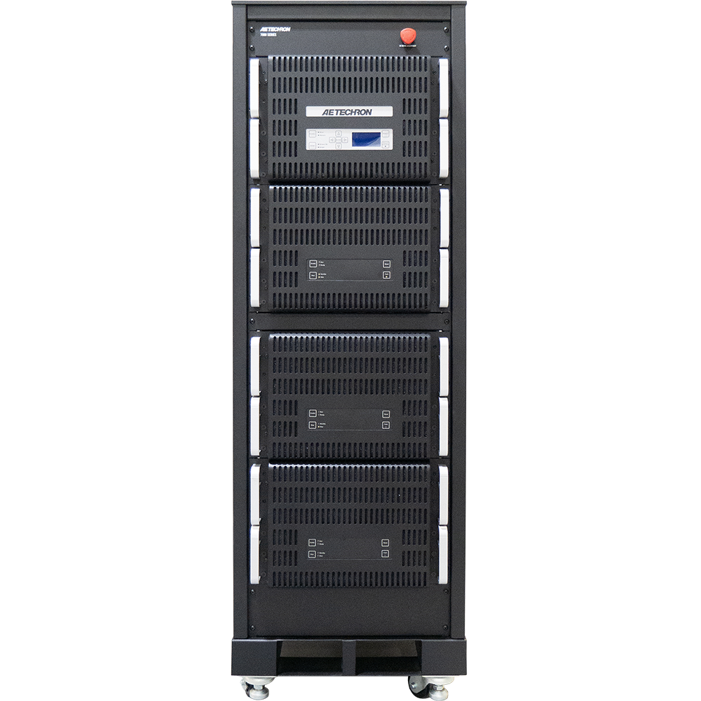
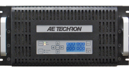
7820-50-400
50V RMS, 400A RMS, DC to 60 kHz
7820-50-400
High-power, high-precision, AC/DC linear power amplifier
- Stable when driving a wide range of resistive, inductive or capacitive loads
- Four-quadrant operation (source and sink)
- Field-selectable controlled-voltage or controlled-current operation
- Protection circuitry protects the amplifier from input overloads, improper output connection (including shorted and improper loads), over-temperature, over-current, and supply voltages that are too high or low
Key Performance Capabilities:
- Output Power: Up to 20 kVA continuous, 40 kVA short-term
- Current: Up to 400A continuous, 800A short-term
- Voltage: Up to ±350 Vp
- Bandwidth: DC to 60 kHz, ±3 dB
- Slew Rate: 40V/µs
- THD: Less than 0.25% (DC to 20 kHz)
- DC Drift: Less than ±400 µV (from room temperature to thermal shutdown)

OVERVIEW
AE Techron’s 7820 Series AC power amplifiers are durable, four-quadrant, DC-enabled, low-noise, wide-bandwidth amplifiers. This combination of features and capabilities makes them a great choice for a large number of research and industrial applications. 7820 series amplifiers are a great solution if bandwidth and/or system noise is a problem. They are able to drive low-impedance loads at frequencies of up to 60kHz.
Because they utilize a linear circuit topology, AE Techron 7820 series amplifiers have no switching noise in their output and very low radiated EMI. This results in THD and noise floors that are much lower than what is possible with traditional switch mode amplifiers, making them ideal for applications that require either high precision or, because of sensitive measurements, cannot tolerate the radiated noise associated with switch mode amplifiers.
7820 series amplifiers are tough, both physically and electrically. 7820 series models have been used for conducting experiments on a Navy warship, controlling a magnetic field in a fusion experiment, and driving DUTs while absorbing back EMF when there is a failure.
The 7820 series is designed and built for applications where large surge currents or long duration power is needed. This makes them ideal for applications where power or duty cycle requirements are greater than is possible with consumer- or pro-audio-grade amplifiers. Because power ratings are continuous, AE Techron amplifiers often produce between 4 and 8 times more power than a similarly rated consumer amplifier.
The 7820 Series consists of three amplifier models: 7820-50-400, 7820-100-200 and 7820-200-100. Each model has been optimized for specific load impedances, from 0.1 ohm to 8 ohms. Customized versions can be ordered with special amplifier configurations and/or with extra rack space to install additional equipment. Contact us today; let us see if we can create a custom configuration specifically to meet your needs.
OUTPUT CHART
Note: Testing performed into resistive loads as specified. Performance reported is typical into the specified load up to 20 kHz frequency levels. Performance may be affected when operating into highly reactive loads or above 20 kHz, reducing maximum voltage, current and power output.
| PEAK OUTPUT | RMS OUTPUT | ||||||||||
| 40mSec Pulse, 20% Duty Cycle |
5 Min, 100% Duty Cycle |
1 Hr, 100% Duty Cycle |
5 Min, 100% Duty Cycle |
1 Hr, 100% Duty Cycle |
|||||||
| Ohms | Volts | Amps | Volts | Amps | Volts | Amps | Volts | Amps | Volts | Amps | Watts |
| 1 | 98 | 104 | 98 | 104 | 97 | 104 | 69 | 72 | 69 | 72 | 4968 |
| 2 | 95 | 92 | 95 | 92 | 95 | 92 | 66 | 64 | 66 | 64 | 4224 |
| 0.5 | 88 | 176 | 88 | 176 | 88 | 176 | 60 | 120 | 60 | 120 | 7200 |
| 0.25 | 81 | 324 | 81 | 324 | 81 | 324 | 56 | 224 | 56 | 224 | 12544 |
| 0.125 | 72 | 576 | 72 | 576 | 72 | 576 | 50 | 400 | 50 | 400 | 20000 |
| 0.0625 | 50 | 840 | 32 | 536 | 32 | 536 | 23 | 364 | 23 | 364 | 8372 |
| 0.03125 | 23 | 788 | 23 | 776 | 23 | 764 | 16 | 532 | 16 | 520 | 8320 |
SPECIFICATIONS
Performance Specifications
Testing performed at 208V/415V AC. 7800 series amplifiers can operate from 400V AC ±10%. Since these amplifiers have an unregulated power supply, low line conditions may slightly affect the maximum voltage potential. All testing was performed in Controlled-Voltage (CV) mode. Accuracy was measured when driven into a 10-ohm load with between 0.1V DC and 6V DC or between 0.2V AC and 5V AC presented at its inputs.
- Output Range: -95Vp to +95Vp
- Output Current: 0A to 400A RMS continuous
- Maximum Continuous Output Power: 20 kW RMS
- Peak Current: 840A for 40 ms
- Slew Rate: 40 V/µs
- Supply Voltage: 3-phase 208V ±10%, 120A, 50/60 Hz; 400V, 60A version available
- Bandwidth (-3dB): DC to 60 kHz
- Phase Response (10 Hz – 10 kHz): ±8.3 degrees
- Unit to Unit Phase Error: ±0.1 degrees at 60 Hz
- Output Offset: <±200 µV
- Output Offset Current: <10 mA, DC
- Residual Noise, 10 Hz to 20 kHz: <250 µV (<0.25 mV)
- THD (DC – 20 kHz): <0.25%
- DC Drift,
- From Cold to Maximum Operating Temperature: <±400 µV
- After 20 Minutes of Operation: ±200 µV
- Output Impedance: 3.2 mΩ in Series with 2.2 µH
Input Characteristics
- Unbalanced BNC connector: 10 kΩ single-ended
- Gain,
- Voltage Mode: 80 volts/volt
- Current Mode: 80 amperes/volt
- Gain Linearity (over input signal, from 0.2V to 5V),
- DC: 0.0125%
- AC: 0.030%
- Max Input Voltage: ±10V, balanced or unbalanced
- Input Impedance: 20 kΩ differential
- Input Sensitivity: 3.0V input for 3800W output into 1 ohm, adjustable
- Common Mode Rejection Range: ±11V DC maximum
- Common Mode Rejection Ratio: Better than 70 dB
Status Display, Control, I/O
- Front Panel LED Displays indicate: Ready, Standby, Fault
- Soft Touch Switches for: Run, Stop, Reset
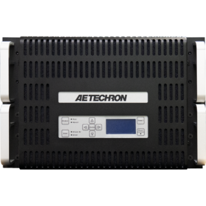
- LCD Display: Can be configured for up to four simultaneous displays reporting one, two, or all four of the following: Vp, VRMS, Ap, ARMS. Also reports any fault conditions that occur and suggests corrective action.
- Back Panel Power Connection: Barrier strip
- Signal Output: Back-panel high-current connectors
- Signal Input: Back-panel unbalanced BNC
Communication Capabilities
- Reporting: System Fault, Over Temp, Over Voltage, Over Load
Protection
- Over/Under Voltage: ±10% from specified supply voltage amplifier is forced to Standby
- Over Current: Breaker protection on both main power and low-voltage supplies
- Over Temperature: Separate output transistor, heat sink, and transformer temperature monitoring and protection
Physical Characteristics
- Chassis: Black powder-coated heavy-duty steel frame and panels
- Operating Temperature: 10°C to 50°C (50°F to 122°F), maximum output power de-rated above 30°C (86°F).)
- Humidity: 70% or less, non-condensing
- Cooling: Forced air cooling from front to back through filters via six 100ft3/min. fans
- Dimensions (HxWxD): 64.6 x 22.6 x 31.6 in. (164.1 x 57.4 x 80.3 cm)
- Weight: Approximately 850 lbs. (386 kg)

