7794MRL: Up to 200 Ap/100 Vp, Voltage or Current Source, Three-Phase

The AE Techron 7794MRL gradient amplifier provides a solution for the unique requirements of Low-Field and Ultra-Low-Field MRI.
AE Techron is an industry pioneer in MRI. Our engineers developed some of the first commercially available gradient
amplifiers ever made. We bring this experience to the design of every new gradient amplifier in our product line.
One key differentiation of AE Techron gradient amplifiers compared to typical gradient amplifiers from other suppliers is the 7794MRL’s very-low-noise linear topology. A key benefit of this approach is the elimination of switching noises, which makes it possible to achieve good image quality with magnetic fields below 100 mT.
Never satisfied with the performance of our products, we were excited when we were approached by leaders in the low-field MRI community and asked to work with them to develop an improved Low-Field Gradient amplifier that would allow them to achieve faster rise times and better images at ever lower field strengths.
The 7794MRL is the result of this cooperative development effort. By further reducing the already low system non-linearities found in our 2100 series MRI systems, the AE Techron 7794MRL is able to be used successfully in research systems with field strengths as low as an amazing 6 mT.
The 7794MRL also possesses a number of important physical attributes. It combines a small footprint, integrated power supply/amplifier design, rugged construction and modest weight, to make it a great choice for field-deployable, low-field or small-bore MRI systems.
Contact us directly or contact your local AE Techron sales partner to see if we can support your latest project with its special requirements in ways other suppliers can’t or simply choose not to.
7794MRL
High-power gradient amplifier plus integrated power supply
- Four-quadrant linear design.
- Blanking feature lowers the noise floor on the amplifier by shutting down the output stage. This action occurs in less than 10 µs.
- Robust, linear power supply results in extremely low noise; bi-level switch design limits heat dissipation to output devices.
- Provides precision control of output offset, DC drift and gain linearity.
Key Performance Capabilities:
- Up to 200 Ap, 100 Vp
- Current-mode response: DC-5 kHz (compensation dependent); Voltage-mode response: DC-20 kHz at rated power.
- Noise Floor (when Blanking circuit is enabled): 5 µA or less
- Current Settling Time on ramp of 0A to ±50A or ±50A to 0A: 100 µs to within 1.0A or 1%; 175 µs to within 200 mA or 0.2%
Importance of Low Noise Gradient Amps in Low Field MRI
Here is a
link to the video on our local server.
Output
Pulsed Output
Pulse testing performed with unit operated in Controlled-Current mode with a load equal to 140 µH + 100 mΩ and at 25°C ambient temperature. *DC 1Ω.
| Output (±A Peak) | PULSE DURATION / OFF TIME (ms) |
||||||
| ∞DC* | 500 / 500 | 100 / 100 | 10 /20 | 170 / 1000 | 25 / 1000 | 4 / 100 | |
| 160 | 200 | 200 | 200 | 200 | 200 | 200 | |
Specifications
Performance
Specification typical at 25°C ambient. Unless otherwise noted; testing was done in Current mode with a load = 140 µH +100 mΩ
Peak Current Limit: 200A
Gain Linearity,*
DC: 0.0125% (over input signal, from 0.2V to 5V)
AC: 0.030%
Output Offset (adjustable to zero),
Voltage Mode: Less than ±400 µV
Current Mode: ±5 mA
Output Impedance,
Current Mode (effective): 2000Ω
Voltage Mode (typical): 3 mΩ in series with 2.23 µH
Load,
Current Mode: 500 µH + 1200 µΩ
Adaptable Range: 5 µH to 2.5 H, 0.01Ω to 20Ω
Current Mode Response: −3 dB at 5 kHz (compensation dependent)
Current Settling Time, Ramp 0A to ±50A or ±50A to 0A,
100 µs:To within 1.0A or 1%
175 µs: To within 200 mA or 0.2%
Total Harmonic Distortion,
Current Mode: Less than 0.1%
Load: 140 µH + 100 mΩ
Noise Floor:
200 µA or less
5 µA or less (when Blanking circuit is enabled)
DC Drift, Self Heating Drift, 0 to ±60A: 5 mA/10 minutes, maximum
Noise Output,
10 Hz to 1 kHz: 0.2 mA
1 kHz to 60 kHz: 0.05 mA
Signal-to-Noise Ratio:
-110 dBA
Ripple Noise Output:
none
Slew Rate, Voltage Mode:
4.5 V/µs
*Gain Linearity Accuracy was measured in Voltage mode with the amplifier driven into a 10Ω load with between 0.1VDC and 6VDC or between 0.2VAC and 5VAC presented at its inputs.
Input Characteristics
Three-Terminal Barrier Block Connector: Balanced with ground, 20kΩ differential
BNC Connector: Unbalanced, 10kΩ single ended
Max Input Voltage:
±10V, balanced or unbalanced
Common Mode Rejection: -58 dB with 5V input
Status Display, Control, I/O
LCD Display (front panel): Status Indicators (front panel): LEDs indicate a status of Run, Ready, or Standby, and Fault conditions
Status Indicators (front panel): LEDs indicate a status of Run, Ready, or Standby, and Fault conditions
Controls (front panel): Soft-touch Switches for Run (Enable), Stop and Reset functions
Controls (back panel): Dual-function AC mains power switch and circuit breaker; rating: 30A for 208 volts or 15A for 400 volts. Turn off and then back on to reset
Connectors (back panel),
Power Connection: NEMA-style locking receptacle; matching AC connector also included
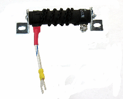
Signal Output: 4-position terminal barrier block (OUTPUT/COMMON/ SAMPLED COMMON/CHASSIS GROUND); resistor between SAMPLED COMMON and CHASSIS GROUND terminals is a 2.7-ohm, 2W, 5%, metal-oxide resistor
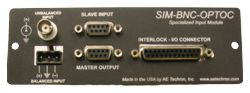
Signal Input: User-selectable BNC or Barrier Strip, balanced or unbalanced
Interlock I/O Connection: 25-pin D connector provides for remote monitoring and control functions
Remote Control and Monitoring
(via back-panel D connector)
Current Monitor: 20A/V ± 1%; 10A/V ± 1% (differential configuration)
Reporting: System Fault, Over Temp, Over Voltage, Over Load
Control: Blanking control, Force to Standby, Remove from Standby, Reset after a fault
Amplifier Protection
Over Load/Distortion (IOC): Shutdown or clipped output
Current vs. Time (ODEP): Clipped output
Each heat-sink temperature: Shutdown 105°C
Overvoltage Shutdown: 229 VAC / 440 VAC
Undervoltage Shutdown: 187 VAC / 360 VAC
Operation Requirements
AC Power Source: Three-phase, 208 VAC ±10%, 47-60 Hz, 30 Amp AC service; (400 VAC ±10%, 15 Amp service model available)
Environmental,
Operating Temperature: +10°C to +50°C (+50°F to +122°F); Maximum output poewr de-rated above 30°C (86°F)
Storage: –30°C to +85°C (–22°F to +185°F)
Humidity: 70% or less, non-condensing
Physical Characteristics
Dimensions (HxWxD): 12.25” x 19” x 22.8” (31.1 cm x 48.3 cm x 57.9 cm)
Cooling: Forced air cooling from front to back through removable filters via six 100 CFM fans. No space is required between rack-mounted amplifiers. Air filters are removable from the rear via one fastener per side and may be eliminated if cabinet filtration is provided.
Airflow: 600CFM
Weight: 153 lbs (69 kg)
Shipping Weight: 158 lbs (71.7 kg)
Front & Back


Downloads
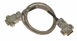
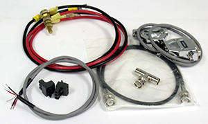
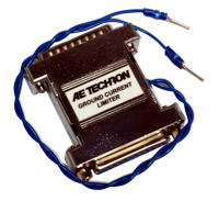
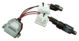
Recommended Accessories
Want to discuss a product or application?
Our knowledgeable sales and support staff can help find the right system for your needs.
We're the audio-bandwidth experts.